Plunger Upstroke

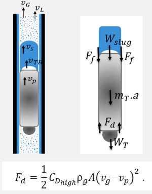
The plungers upstroke movement creates a sealing between gas and liquid phases. A surfacing plunger deliquify the well with each cycle.

Higher shut-in times are used for the intermittent gas lift and conventional plunger lift cases to build-up a pressure in the casing to lift accumulated liquid and plunger.

Little to no shut-in time is required for continuous flow plunger lift. The plunger and liquid slug are lifted with drag force generated by gas and liquid flow.

No plunger

Conventional Plunger (GAPL)

Continuous Flow (PAGL)

Two-piece plunger upstroke

Continuous Flow Plunger Lift Upstroke


Understanding the mechanics of the continuous flow plunger (CFP) lift upstroke stage is important to

  • Develop an operational envelope for CFP lift and PAGL at the design stage.
  • Plunger selection
  • Shut-in/after-flow time settings
  • Gas injection optimization


The main parameters are considered as

  • Liquid unloading
    • Gravitational pressure loss
    • Slug growth
    • Liquid fallback
  • Upstroke duration
    • Plunger upstroke velocity
  • GLR and gas lift


Continuous flow plunger upstroke relies on drag force generated by the flow. The drag lifts the plunger and the liquid slug on top of it. Using force balance equation, a dimensionless parameter drag coefficient is retrieved. The drag coefficient is denoted as CDhigh for the merged two-piece plunger and closed bypass plunger.

Instantaneous upstroke

Instantaneous upstroke is shown in the slow-motion video on the right. Initially, the ball sitting on BHA, and the sleeve is falling. As ball and sleeve merge, they upstroke without any delay.

The two-piece plungers that started the upstroke were observed to be surfacing without stalling in the experiments.

If the flow rate was insufficient, no upstroke movement was made. Two-piece plunger sitting on BHA do not build-up pressure at the casing. Increase gas flow rate or shut-in well for Pcasing buildup would be required to send two-piece plunger up.

Conventional plunger lift upstroke

Starts upstroke with liquid slug

      Liquid fallback is an important consideration


Continuous flow plunger lift upstroke

Catches liquid along the way

      Stationary or falling liquid film

      Removal of hydrostatic backpressure before liquid loading conditions

Increased slug weight slows down the plunger

The gas expansion increases the drag force hence vplunger

Plunger Upstroke Model


Continuous flow plunger lift upstroke model methodology provides plunger velocity calculation iteratively with the consideration of CDhigh, hL , vL for each segment of the well. The liquid slug growth calculated for each segment starting from the BHA to the surface.


Key outputs

Upstroke velocity profile

Kinetic energy at impact

Liquid slug removal

Hydrostatic pressure

Upstroke Experiments


Heavier plungers surface slower due to higher weight. The models are capable to consider this effect for upstroke velocity estimations

6-in height

1.88-in OD

9-in height

1.88-in OD

Plunger OD increases the upstroke velocity. As the outer diameter of the plunger increase, the orifice between the plunger and the tubing decreases. This increases the drag coefficient of the plunger hence increasing upstroke velocity.

6-in height

1.88-in OD

6-in height

1.90-in OD

Continuous Flow Plunger Lift Upstroke Hydrodynamics

Continuous Flow Plunger Lift hydrodynamics is influenced by

  • Multiphase flow
  • Plunger specs

Drag based upstroke model showed a fair match

  • Estimation of vplunger, liquid slug
  • Provides operational boundary for PAGL
  • operation and different plunger types