
Plunger Lift Design Stage
-
✓
When to deploy?Operational boundaries
Continuous to conventional transition - ✓
-
✓
Cycle optimizationShut-in / After-flow times
- ✓
Operational Boundaries
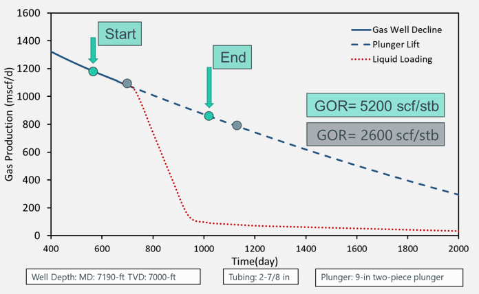
The mechanistic models developed for fall and upstroke stages of plunger lift provides the operational boundaries. The figures show the operational boundaries, for given multiphase flow conditions, plungers and shut-in/after-flow time settings.
– The start point* shows the maximum flow rate to fall against for given conditions.
– The end point* is the least flow rate required for two-piece plunger to upstroke.
* Please note that those flow rate requirements change significantly with different flow, well schematic conditions.
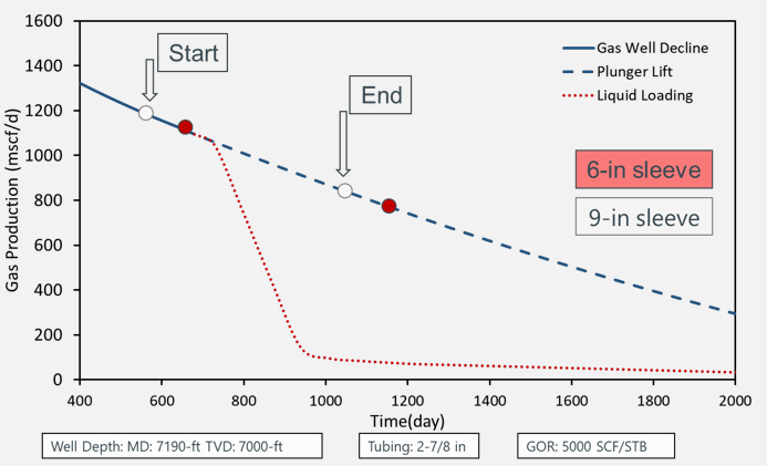
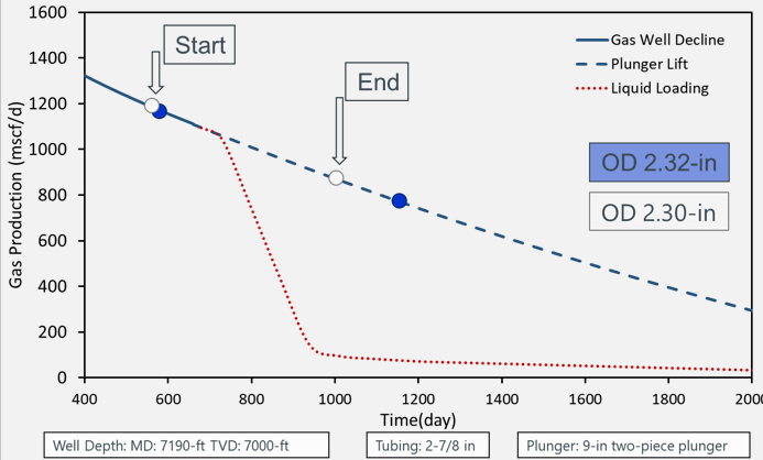
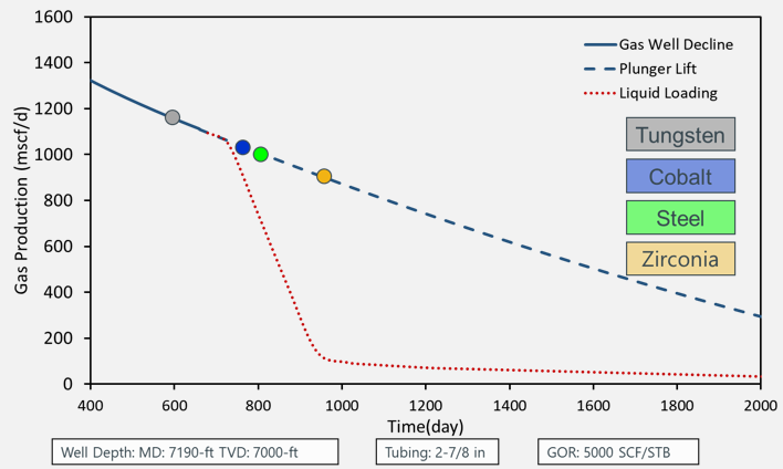
Plunger Selection
Each plunger offer different fall rates, and liquid sweeping capabilities during the upstroke. The fluid properties, sand, tubing properties and well schematic (DLS) may limit the application of some plungers. For instance, 6-in sleeve and 15-in bypass plunger may offer similar fall rates. Based on the optimization needs, the plunger selection can be made with the plunger lift software recommendations.
– The start point* shows the max. flow rate to fall against for given conditions.
– The end point* is the min. flow rate required for two-piece plunger to upstroke.
* Please note that those flow rate requirements change significantly with different flow, well schematic conditions.
Cycle Optimization
The shut-in time is an important consideration for fall stage and pressure build-up for conventional plungers.
Introducing shut-in time would increase the fall velocity of continuous flow plungers significantly.
The pressure build-up profile is important to decide the shut-in time for conventional plungers. Based on the shut-in time, plunger selection may be changed. If a well needs high shut-in due to pressure build-up, then a slower fall velocity plungers can be selected.
The after-flow stage is when the well produce oil, gas and water after the plunger upstroke. After plunger unloads the well, it is advised to produce until the liquid loading decreases the production.
The continuous flow plunger lift does not require extended after-flow time if there is little to no shut-in time. For two-piece plungers, the after-flow time serve as ‘separation time’ between ball and sleeve.
For conventional plunger lift, a higher after-flow time may cause increased liquid loading which would require higher pressure build-up to surface the plunger. The shut-in and after-flow time are optimized collectively.
Production Optimization
The optimizing the production is typically the main goal for plunger lift operations. The methodology focuses on improving the daily production instead of the production per cycle.
The plunger lift software’s provides gas lift sensitivity analysis which can be used to reduce gas injection amounts. For different gas injection rates, the plunger lift tools estimate bottomhole pressure, production rates.
Forecast
The mechanistic models for both continuous flow and conventional plunger lift provides valuable information on how much liquid the plunger lift operation unloads. This offers the change in the outflow performance curve for given plunger lifted wells hence nodal analysis.
Using the reservoir pressure decline, future IPR or production forecasts, the plunger lift simulations can be done for the future dates.