Plunger Fall Velocity
During the shut-in plungers fall against
-
static gas (i)
-
static gas with liquid film (ii)
-
liquid column (iii)
static gas (i)
static gas with liquid film (ii)
liquid column (iii)
multiphase flow (iv)
The rules of thumb numbers do not provide accurate fall velocity estimations.
Measuring fall velocity and using it for different wells are not applicable as many parameters change between each well and plunger lift operation.
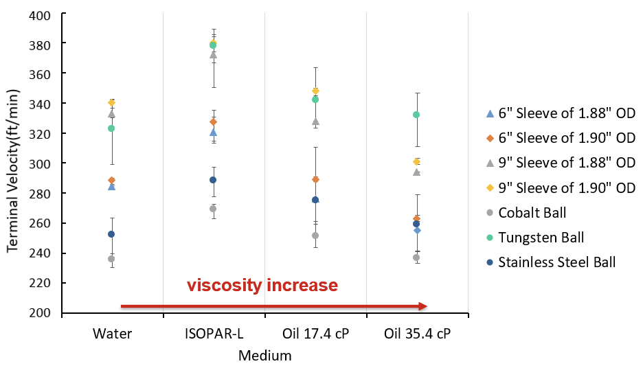
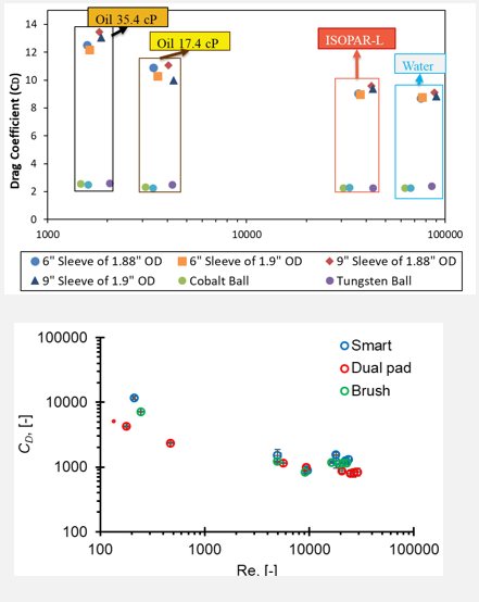
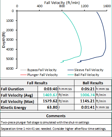
In Figure the vfall (fall velocity) in different mediums are shown. With higher viscosity slower fall velocity may be expected but other fluid properties influence the vfall.
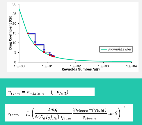
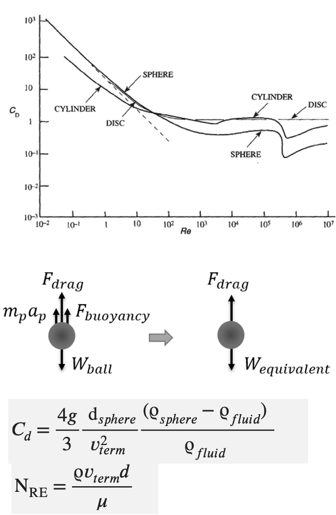
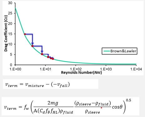
Dimensionless parameters are suitable to characterize the fall mechanics of falling particles. Drag coefficient (CD) to Reynolds (Re) number plots for common shapes are shown in the Figure. Reynolds number includes flow properties whereas the drag coefficient represents the drag characteristic of falling particles.
Drag coefficients can be retrieved from fall experiments, field measurements, and CFD. Terminal fall velocity is the highest attainable velocity that particle fall in a given fluid. When plungers reach terminal velocity, acceleration is assumed to be zero. Applying force balance with the consideration of buoyancy, the drag and gravitational forces become equal and the drag coefficient is retrieved.
The literature on plunger drag coefficient for fall stage consist; Sayman (2019), Akhiiartdinov (2021), Nadkrynechny et al. (2013), and Acosta (2016).
Conventional plungers have significantly higher drag coefficient values compared to two-piece and bypass plungers. The lack of inner orifice for conventional plungers limit their fall motion. This type of plungers can only fall when the well is shut-in. Depending on the type of conventional plunger, the required shut-in times may increase.
The continuous flow plungers can fall against flowing well. The operational boundaries for fall stage depends on the plunger type, multiphase flow conditions, well schematic, fluid properties. Both bypass and two-piece plunger can be used with shut-in well which may result in excessive plunger fall velocity.
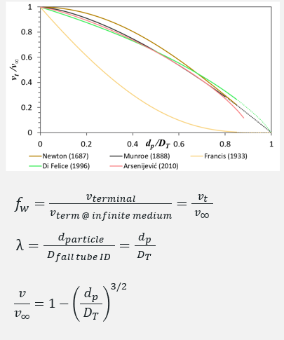
The drag coefficient of sphere particles at infinite medium has been studied extensively in the literature. For the plunger lift operation, the wall effect must be considered. Wall exerts a retarding effect on vterminal.
Wall effect correlation for spherical particles shows that the terminal fall velocity decreases with a higher diameter ratio. Wall Factor (fw) is defined as terminal velocity with wall effect divided by the terminal velocity at infinite medium. Diameter Ratio (λ) is the diameter of the particle over the tubing ID.
The accuracy of correlations changes with Re and diameter ratio. Munroe’s wall effect correlation is reported to be applicable in high RE and high diameter ratios which represent field conditions for plunger lift operation.
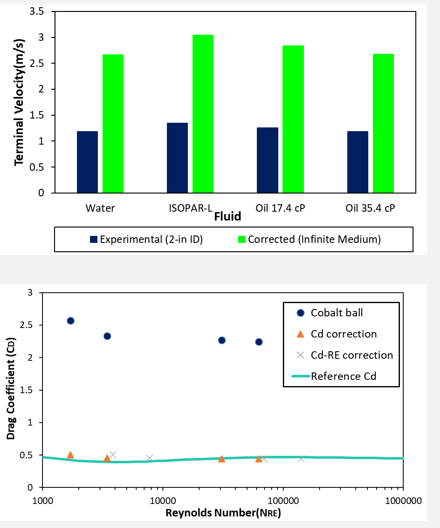
Using the measured fall velocity for 2-in ID tubing, and applying the wall effect correlations, one can reach terminal fall velocity for infinite medium shown in the figure.
The wall effect methodology can be used in both ways. You can take a reference cd for infinite medium and then apply your diameter ratio to find the drag coefficients with the wall effect. This method suggests that there would not need to test different sized balls.
The fall model utilized to estimate fall velocities of different sized balls for 2-3/8 in OD pipe can be seen in the graph. Typically, 1.37-in OD balls are supplied by vendors for 2-3/8 in tubing, but a smaller (1-in) diameter ball can fall faster and extend operational boundary for this case.
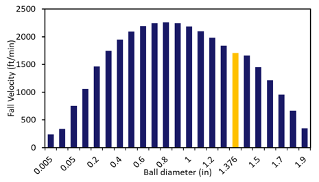
Typically, if there is no wall, a larger diameter ball would fall faster due to volume/weight increase is higher than drag area increase. Initially you can see fall velocity increasing in the bar plot. The wall effect retard the fall velocity as the diameter of ball increases and this effect become more influential around 0.9-in ball OD for given case.
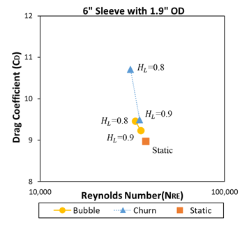
Sayman et al. (2020) presented that with a higher gas injected to static column, the drag coefficient of sleeves increased.
The behavior was found same for all test fluids.
Eccentric fall decreased CD for low viscosity fluids with more gas injected.
CD increase in churn flow conditions for sleeves
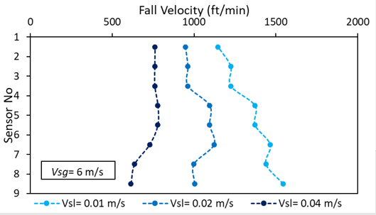
The facility had 30 ft-long test section and compressed air and ISOPAR-L was used to test multiphase flow effects on plunger fall stage.
In the left, fall velocity comparison for three different liquid injection rates and same gas injection rate tested. Increased liquid injection rate resulted in higher liquid holdup and higher mixture density. Increased density reduced the fall velocity of 9-in sleeve.
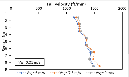
In the right, different gas injection rates tested. If there were no change in the liquid holdup, one would expect slower fall velocity against higher gas flow rate. The increased gas flow rate reduce the liquid holdup which decreases the drag. However, the increased gas flow rate also increases the drag force. Both effects were seen in the fall velocity results.
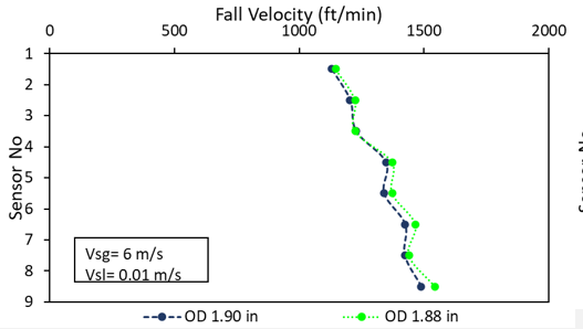
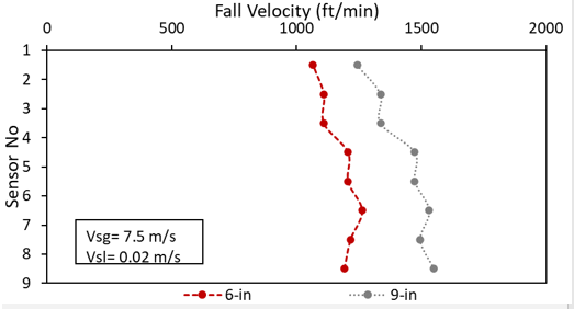
The height, outer diameter (OD), orifice dimension influence the fall velocity.
In the left we have two plunger with 1.90-in OD and 1.88-in OD. Outer diameter decrease the fall velocity marginally.
In the next plot, we have two different length sleeve. The both cases tested with same gas and liquid injection rates. 9-in sleeve falls faster than 6-in as its heavier one.
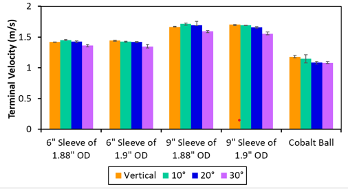
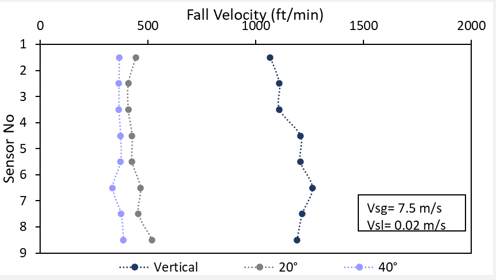
Gravitational force decrease with deviated angles. vfall↑
Liquid holdup increases with higher inclinations which increase the drag force. vfall↑
Eccentric fall occurs and marginally reduce drag force on plunger. vfall↓
Drag coefficient change was marginal in static facility
Liquid holdup change is most influential for dynamic tests for plungers falling against the multiphase flow conditions.
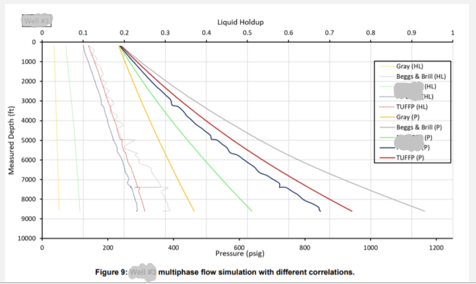
⦾ Corrections for wall effect, two-phase, and deviation
⦾ Iterative calculation
⦾ Well segmentation
⦾ Multiphase flow and fall velocity simulation for each segment
⦾ Influences on key parameters for fall velocity estimation.
⦾ Accurate flow simulation is desired.
⦾ Flow pattern, pressure, gas density, gas velocity, liquid holdup, and more calculated.
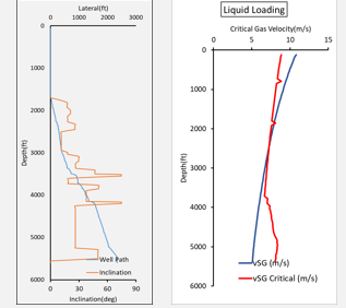
Max flow rate to fall against
Separation time needed
Avoid well integrity problems
Shut-in/afterflow time
Operational boundaries
Multiphase flow conditions
Deliquification
Shut-in/afterflow time